The focused ion beam microscope operates in a similar manner to the scanning electron microscope (SEM) but scans a beam of Ga+ ions instead of electrons. The FIB column accelerates and focuses a beam of Ga+ ions that sputter or mill material from the sample surface in controlled patterns. Sputtering occurs due to the mass of the Ga+ ions that damage the sample surface on impact. Ga+ ions can also be used to deposit patterns of materials such as Pt, C, W, etc. as the ions break apart organic precursor gasses containing the deposited atoms to create protective layers and create complex 3D patterns.
Most modern FIB microscopes are attached as an additional column on SEMs allowing the operator to simultaneously observe and control sample milling with the SEM. The combination of the FIB for milling and the SEM for high resolution imaging enables very delicate site specific sample operations to be performed. The FIB has two primary uses:
FIB tomography
By alternating between imaging and milling the FIB/SEM system can be used to reconstruct a 3D image of the removed material. This technique is inherently destructive but offers great resolution compared to many other tomographic techniques (limited only by the SEM system and the FIB slice thickness). The main limitation is on the size of the reconstructed volume. For sample volumes larger than 20 x 20 x20 µm other tomographic techniques will typically be more suitable.
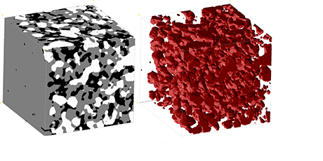
Figure1: 3D visualization of a segmented FIB tomography dataset of a Ni/YSZ fuel cell electrode. (left) Data segmented into pores (black), YSZ (grey) and Ni (white). (right) Surface rendering of the Ni phase. The cube is 10 x 10 x10 µm.
Sample preparation for TEM and large scale facilities
The FIB/SEM system is equipped with a micro manipulator needle and a gas injection system (GIS). These two systems allow finely shaped parts of the bulk sample to be removed and attached using deposition of Pt onto specialized sample holders for other characterization techniques. For synchrotron radiation experiments the FIB/SEM allows preparation of samples with optimal shape and thickness. For TEM experiments the FIB/SEM allows site specific selection of lamella location and the ability to thin the selected lamella to sub 100 nm thicknesses.
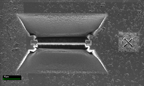
Figure2: A TEM lamella surrounded by trenches before lift out from the sample.
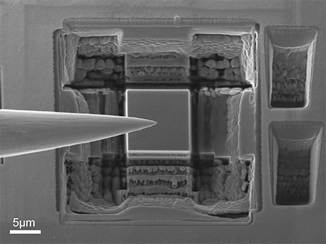
Figure3: A smaller piece of a bulk sample being prepared for a synchrotron experiment. The micromanipulator needle is visible to the left.
Equipment
- Zeiss XB 1540 microscope equipped with SE2 (Everhart-Thornley), In-lens and BSE detectors and an EDS system.
Location: B310, R901
Contact
Karl Thydén, Peter Stanley Jørgensen